Smith Chart Black Magic: Unraveling the Mysteries of Impedance Matching
Associated Articles: Smith Chart Black Magic: Unraveling the Mysteries of Impedance Matching
Introduction
On this auspicious event, we’re delighted to delve into the intriguing subject associated to Smith Chart Black Magic: Unraveling the Mysteries of Impedance Matching. Let’s weave attention-grabbing info and provide contemporary views to the readers.
Desk of Content material
Smith Chart Black Magic: Unraveling the Mysteries of Impedance Matching

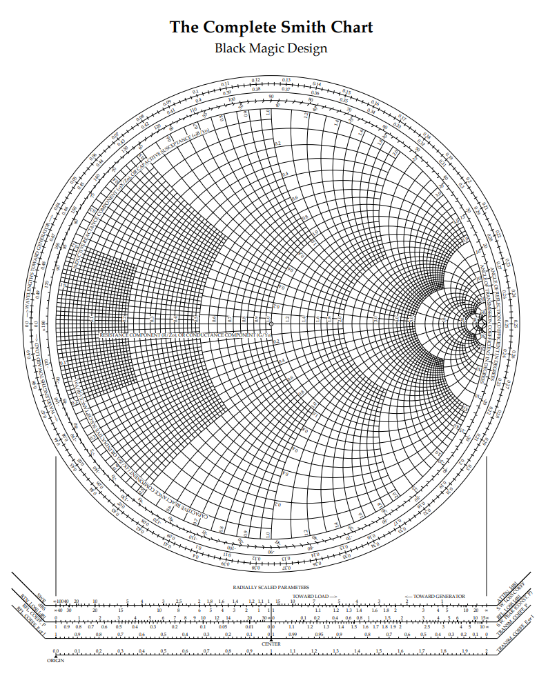
The Smith Chart. To the uninitiated, it is a bewildering swirl of circles and arcs, a seemingly arcane software wielded by RF engineers. To the skilled, it is a highly effective visualization support, a shortcut to complicated calculations, and – dare we are saying it – a type of black magic on the earth of impedance matching. This text delves into the intricacies of the Smith Chart, exploring its underlying rules and demonstrating its sensible functions in microwave and RF circuit design. We’ll transfer past easy impedance transformations and contact upon its less-obvious makes use of, revealing the "black magic" that makes it so efficient.
Understanding the Fundamentals: Impedance and Reflection
Earlier than diving into the chart’s intricacies, let’s set up a agency grasp of the elemental ideas it represents. The Smith Chart is essentially a graphical illustration of the complicated reflection coefficient, Γ (Gamma), which describes how a sign displays at a discontinuity in a transmission line. This discontinuity may very well be a load impedance (ZL) that does not completely match the attribute impedance (Z0) of the transmission line.
The reflection coefficient is outlined as:
Γ = (ZL – Z0) / (ZL + Z0)
The place:
- ZL is the load impedance
- Z0 is the attribute impedance of the transmission line (sometimes 50 ohms)
Γ is a posh quantity, that means it has each magnitude (|Γ|) and section (∠Γ). The magnitude represents the power of the reflection, starting from 0 (excellent match, no reflection) to 1 (full reflection). The section signifies the timing of the mirrored wave relative to the incident wave.
The Smith Chart’s Geometry: Circles and Arcs of Energy
The genius of the Smith Chart lies in its intelligent mapping of this complicated reflection coefficient onto a normalized impedance airplane. The chart is a circle with a radius of 1, representing the utmost attainable reflection coefficient magnitude.
-
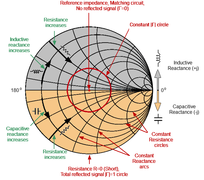
Fixed Resistance Circles: These are circles centered on the horizontal axis (the actual a part of Γ), representing fixed values of normalized resistance (R/Z0). A resistance of 1 (matched impedance) lies on the middle of the chart.
-
Fixed Reactance Circles: These are circles centered on the vertical axis (the imaginary a part of Γ), representing fixed values of normalized reactance (X/Z0). Constructive reactance (inductive) lies above the horizontal axis, and detrimental reactance (capacitive) lies beneath.
-
The Outer Perimeter: Represents a mirrored image coefficient magnitude of 1, indicating an entire reflection.
The fantastic thing about this geometric illustration lies in its capacity to visually signify complicated impedance transformations. Shifting alongside a continuing resistance circle adjustments solely the reactance, whereas transferring alongside a continuing reactance circle adjustments solely the resistance. This simplifies the evaluation of complicated circuits.
Smith Chart Functions: Past the Fundamentals
Whereas the Smith Chart’s major operate is impedance matching, its functions lengthen far past this primary use. Listed here are some examples demonstrating its "black magic":
-
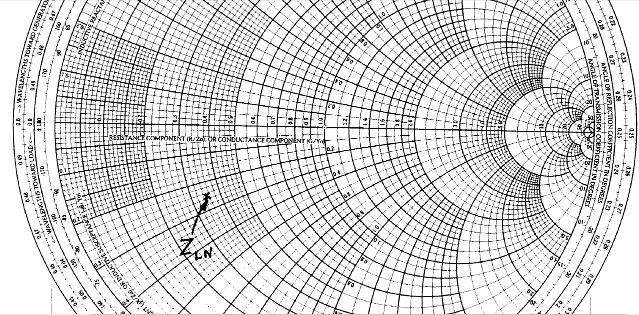
Impedance Matching with Lumped Components: Maybe the most typical utility is designing matching networks utilizing inductors and capacitors. By plotting the load impedance and the specified impedance (often 50 ohms), the Smith Chart permits you to visually decide the values of the required parts to rework the impedance alongside the fixed resistance circles and reactance arcs.
-
Transmission Line Transformations: The Smith Chart may also account for the impact of transmission line size on impedance. Rotating across the chart’s perimeter corresponds to transferring alongside a transmission line. This enables engineers to find out the impedance at any level alongside the road, a vital facet in designing microwave circuits.
-
Admittance Matching: The Smith Chart can be utilized equally nicely for admittance (Y = 1/Z) matching. Merely use the chart’s outer scale to learn admittance values immediately.
-
Stability Evaluation: For amplifiers and oscillators, the Smith Chart is invaluable in figuring out stability and discovering secure working factors. By plotting the enter and output impedances, you’ll be able to visually assess the steadiness of the circuit.
-
S-Parameter Evaluation: The Smith Chart can be utilized to signify S-parameters, which characterize the scattering habits of a community. This enables for a visible illustration of the community’s efficiency beneath completely different situations.
-
Antenna Design: Antenna impedance matching is essential for environment friendly energy switch. The Smith Chart gives a visible support in designing matching networks for antennas, making certain most energy is radiated.
Superior Strategies: Unlocking the Chart’s Full Potential
The true "black magic" of the Smith Chart lies in its capacity to simplify complicated calculations. Listed here are some superior strategies that leverage its energy:
-
Utilizing the Chart for A number of Element Matching: Cascading a number of matching networks might be simply analyzed on the Smith Chart, permitting for the design of extra complicated matching networks.
-
Figuring out Bandwidth: The Smith Chart can be utilized to visually decide the bandwidth of an identical community, a vital parameter for a lot of functions.
-
Analyzing Microstrip Strains: The Smith Chart can be utilized to design microstrip strains and different planar transmission strains, accounting for the results of substrate dielectric fixed and line width.
-
Simulation and Design Software program Integration: Trendy RF design software program packages typically incorporate the Smith Chart, permitting for a seamless integration of visible evaluation with numerical simulation.
Conclusion: The Enduring Legacy of the Smith Chart
The Smith Chart, regardless of its seemingly arcane look, stays an indispensable software for RF and microwave engineers. Its capacity to visually signify complicated impedance transformations, simplify calculations, and supply insights into circuit habits makes it a cornerstone of contemporary RF design. Whereas subtle software program packages provide highly effective simulation capabilities, the Smith Chart’s intuitive graphical illustration continues to supply a priceless and insightful perspective on impedance matching and associated ideas. Mastering the Smith Chart is not nearly memorizing circles and arcs; it is about understanding the underlying rules of reflection, impedance, and transmission line principle, permitting engineers to unlock its full potential and carry out what may look like "black magic" to the uninitiated. The enduring legacy of this seemingly easy chart lies in its capacity to bridge the hole between principle and apply, making complicated RF design issues extra accessible and manageable. It’s a testomony to the ability of chic visualization in tackling complicated engineering challenges.


Closure
Thus, we hope this text has offered priceless insights into Smith Chart Black Magic: Unraveling the Mysteries of Impedance Matching. We respect your consideration to our article. See you in our subsequent article!