Unveiling the Black Magic: A Deep Dive into Full Smith Chart Design
Associated Articles: Unveiling the Black Magic: A Deep Dive into Full Smith Chart Design
Introduction
With enthusiasm, let’s navigate via the intriguing matter associated to Unveiling the Black Magic: A Deep Dive into Full Smith Chart Design. Let’s weave fascinating data and supply contemporary views to the readers.
Desk of Content material
Unveiling the Black Magic: A Deep Dive into Full Smith Chart Design

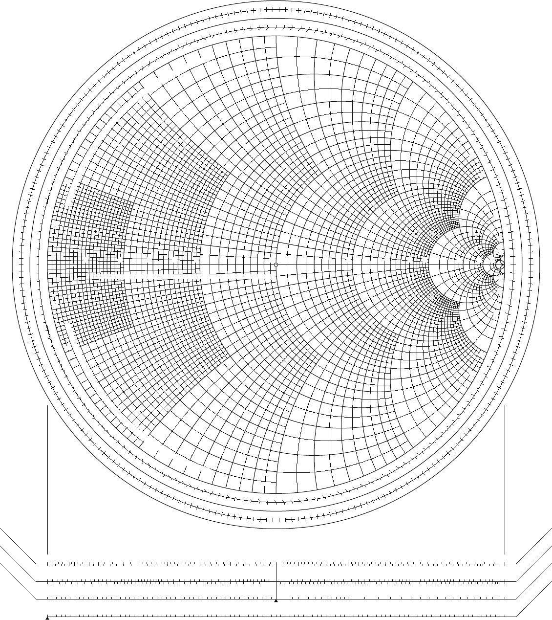
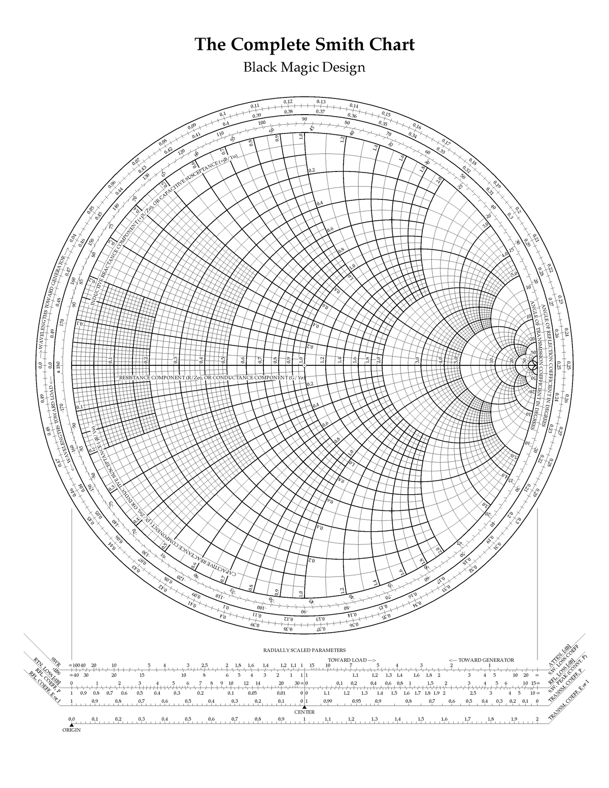
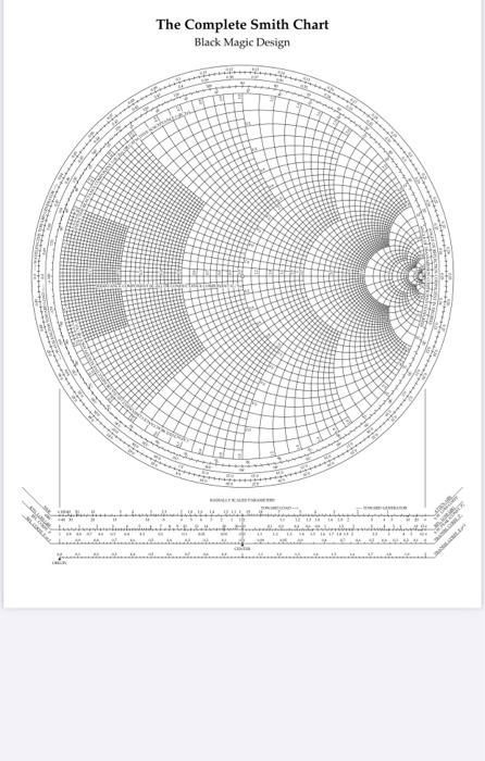
The Smith Chart, a seemingly easy graphical instrument, is a cornerstone of high-frequency circuit design. Its magnificence lies in its capability to symbolize complicated impedance and admittance values on a single, normalized airplane, simplifying the evaluation and design of transmission traces, matching networks, and different RF parts. Whereas usually described as a "black field" by newcomers, understanding its underlying rules unlocks highly effective design capabilities, enabling the creation of subtle circuits with seemingly magical precision. This text delves into the entire Smith chart design course of, revealing the "black magic" behind its effectiveness.
I. Understanding the Fundamentals: Impedance, Admittance, and Normalization
Earlier than embarking on complicated designs, greedy the core ideas is essential. The Smith chart operates on the rules of complicated impedance (Z) and admittance (Y), that are reciprocals (Y = 1/Z). These values are sometimes represented as:
- Z = R + jX: the place R is resistance and X is reactance (inductive or capacitive).
- Y = G + jB: the place G is conductance and B is susceptance.
The important thing to the Smith chart’s effectivity is normalization. All impedance and admittance values are normalized to a attribute impedance (Z₀), often 50 ohms in lots of RF techniques. This normalization permits the chart to symbolize a variety of impedances on a set scale, simplifying calculations and comparisons. The normalized impedance (z) and admittance (y) are:
- z = Z/Z₀
- y = Y/Y₀ = 1/z (the place Y₀ = 1/Z₀)
II. The Smith Chart’s Geometry: Circles and Their Significance
The Smith chart’s graphical illustration consists of two households of circles: fixed resistance (or conductance) circles and fixed reactance (or susceptance) circles.
-
Fixed Resistance (R) Circles: These circles are centered on the horizontal axis (actual a part of z) and their radii improve with rising resistance. A circle with radius 1 represents a normalized resistance of 1 (equal to the attribute impedance). The middle of the chart represents a brief circuit (R=0) and the rightmost level represents an open circuit (R=∞).
-
Fixed Reactance (X) Circles: These circles are centered on the rightmost level of the horizontal axis (representing infinite resistance) and their radii range with the magnitude of the reactance. Constructive reactance (inductive) circles are positioned above the horizontal axis, whereas detrimental reactance (capacitive) circles are positioned beneath. The diameter of those circles is proportional to the magnitude of the reactance.
Comparable circles exist for fixed conductance (G) and fixed susceptance (B) within the admittance illustration, however they’re oriented in a different way. Understanding the connection between these circles is important for deciphering impedance transformations.
III. Transmission Line Results and the Smith Chart
One of many Smith chart’s strongest purposes is visualizing the impedance transformation alongside a transmission line. The impedance at a distance ‘l’ from the load impedance (ZL) may be calculated utilizing the next equation:
Z(l) = Z₀ * [(ZL + jZ₀ tan(βl)) / (Z₀ + jZL tan(βl))]
the place β is the propagation fixed of the transmission line.
On the Smith chart, a motion alongside a continuing radius arc from the load impedance level represents the change in impedance alongside the transmission line. A full rotation across the chart represents a half-wavelength (λ/2) change in distance. That is extremely helpful for designing matching networks and understanding standing wave patterns.
IV. Designing Matching Networks: The Artwork of Impedance Transformation
The first utility of the Smith Chart is in designing matching networks. The objective is to rework the load impedance to match the attribute impedance of the transmission line (sometimes 50 ohms) to attenuate reflections and maximize energy switch. This includes strategically putting shunt and collection parts (capacitors and inductors) alongside the transmission line.
The design course of sometimes includes:
-
Plotting the Normalized Load Impedance: Step one is to normalize the load impedance and plot it on the Smith chart.
-
Figuring out the Transformation Path: The designer then identifies a path on the chart that strikes the impedance level in the direction of the middle (Z=Z₀). This includes utilizing the fixed resistance and reactance circles to information the number of parts.
-
Deciding on Elements: Every motion alongside the chart represents the addition of a selected part. Transferring alongside a continuing resistance circle represents including a shunt reactance (capacitor or inductor), whereas shifting alongside a continuing conductance circle represents including a collection reactance.
-
Iteration and Optimization: The method could require a number of iterations to realize the specified impedance match. Smith chart software program instruments usually facilitate this course of.
V. Superior Purposes: Past Easy Matching Networks
The Smith chart’s capabilities lengthen far past easy matching community design. It is a useful instrument for:
-
Analyzing Resonant Circuits: The chart can be utilized to find out resonant frequencies and Q components of resonant circuits.
-
Designing Stub Matchers: Open or short-circuited stubs can be utilized to match impedances, and the Smith chart helps decide the stub size and placement.
-
Analyzing Multiport Networks: Whereas extra complicated, the Smith chart may be tailored to research and design multiport networks.
-
Microwave Circuit Design: It is an indispensable instrument within the design of microwave parts, together with filters, couplers, and energy dividers.
VI. Software program Instruments and Trendy Design Practices
Whereas handbook Smith chart calculations are useful for understanding the underlying rules, fashionable design depends closely on software program instruments that incorporate Smith chart performance. These instruments automate the design course of, permitting for fast prototyping and optimization. They usually embody options like:
-
Automated Part Choice: Software program can routinely choose optimum part values based mostly on the specified impedance transformation.
-
Simulation and Optimization: Superior simulation capabilities permit for correct prediction of circuit efficiency earlier than bodily building.
-
Visualization and Evaluation: Interactive graphical representations of the design course of improve understanding and facilitate troubleshooting.
VII. Conclusion: The Enduring Legacy of the Smith Chart
Regardless of the arrival of subtle computer-aided design (CAD) instruments, the Smith chart stays a useful instrument for RF and microwave engineers. Its graphical nature supplies an intuitive understanding of impedance transformations and circuit habits. Whereas the "black magic" might sound intimidating initially, a radical understanding of its underlying rules empowers designers to create subtle high-frequency circuits with outstanding precision. The Smith chart is not only a instrument; it is a testomony to the elegant interaction of arithmetic and engineering, a timeless legacy on this planet of high-frequency design. It continues to be an important aspect within the schooling and follow of RF and microwave engineering, guaranteeing its enduring relevance within the ever-evolving panorama of electronics. Mastering the Smith chart unlocks a strong toolbox for tackling complicated design challenges and pushing the boundaries of high-frequency know-how.


Closure
Thus, we hope this text has offered useful insights into Unveiling the Black Magic: A Deep Dive into Full Smith Chart Design. We hope you discover this text informative and useful. See you in our subsequent article!